BENEFITS OF INCORPORATING KIT BUILDING INTO AN ELECTRONICS OR MECHATRONICS COURSE:
Whether or not to incorporate kits into an electronics program seems to be a point of contention
amongst electronics instructors. I have heard negative comments such as, “Kits are a waste of
time. The students make a bunch of mistakes trying to put them together, then get frustrated
because they don’t work!”
Personally, I am a great believer in building electronics kits. If
administered effectively, I believe the experience can prove invaluable in providing a hands-on,
“under the hood” experience that is not possible with just breadboarding. If done correctly, kit
building involves both the cognitive and kinesthetic (psychomotor) domains, thus enhancing the
learning process. Assembling, testing and, if necessary, troubleshooting electronic kits might
well be the closest experience a student could have to a day on the job as an electronics or
mechatronics technician.

The New Student’s First Kit Building Experience:
There are many maker/hobbyist DIY (Do it Yourself) electronic kits on the market that are
inexpensive and fun to build. For example, cobbling together a kit that repels mosquitos with
an ultrasonic wave could provide valuable soldering practice and certainly have a practical
application on the back patio.
In fact, building any form of electronic kit could be a positive
experience for the new student, generating enthusiasm and instilling confidence.
A kit such as the mosquito deterrent circuit could possibly work as an introductory build
experience for first term students.
But to make the experience worthwhile in a school laboratory
environment, the instructor must be creative and fill in some gaps, identifying additional
procedural steps that could be performed during the build process. These steps are necessary
to enhance the educational experience. Simply turning students loose with a "Go to it; have
fun!" attitude could end in frustration and disaster. It is human nature to cut corners, not read
instructions, and rush through a process. Left on their own, students might try to assemble a
small kit in one class period, as if the goal were to finish the task as quickly as possible. These
are behaviors we absolutely do not want to instill into future electronics and mechatronics
technicians!
To keep students motivated and engaged, the instructor might consider:
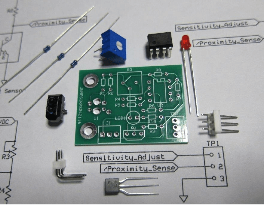
- Dividing the build process into stages, with a specific milestone after each stage. For
example, the students could be expected to identify each resistor contained in a kit by its
color code. They would then be required to measure the ohmic value of each resistor
and determine if it is within tolerance.
- Delivering a brief explanation before embarking on each assembly stage, specifying
educational objectives to be met.
- Where applicable, requiring teacher sign off after completion of a stage. The sign off
could require a demonstration of a competency: "Show me how you measured the
voltage at point B."
- Provide an occasional "Show and tell” moment." While students might not be at a point
in their training where they use an oscilloscope, the instructor could connect the scope to
a student's completed circuit board and show them the 25KHz waveform that annoys the
mosquitos.
While this might seem trivial to the seasoned technician, it could be an
inspirational moment for the new student!
The PRESSON Innovative Approach to Kit Building:
As discussed above, building a DIY kit during an electronics course program can have its
benefits. But PRESSON Circuit Modules, Inc. takes kit building to a new level. Assembly and
testing of PRESSON circuit module kits is an integral process within the company’s PDF
courseware (offered free with each module). Each PRESSON kit becomes the focal point of:
- A very detailed, step-by-step assembly procedure
- A step-by-step testing procedure
- One or more lab/theory lessons containing several experimental procedures involving
that module
- Additional lab/theory lessons in which the module is interfaced with other PRESSON
modules and breadboarded circuitry
Click here to see an excerpt from a PRESSON assembly procedure.
Click here to see an excerpt from a PRESSON theory/lab procedure.

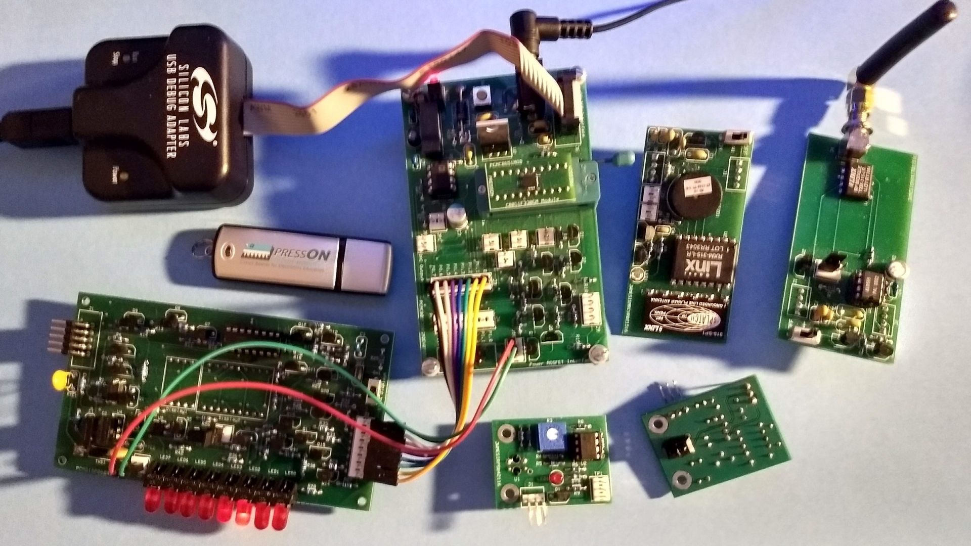
PRESSON kits comprise a family of circuit modules, designed primarily for use in the study of
industrial electronic control systems. Unlike many DIY kits, PRESSON modules are designed
for easy mounting onto grounded base plates and can function directly within an actual control
system. To support their use within an advanced student’s capstone project, or application
within an actual piece of machinery, PRESSON Circuit Modules, Inc. provides a thorough user’s
guide, or data manual for each circuit module. Each guide contains complete schematic
diagrams and a concise, but detailed theory of operation. PRESSON users’ guides and
courseware contain direct hyperlinks to manufacture’s datasheets for the sensors and
integrated circuits contained on the modules.
Click here to see a PRESSON user's guide.
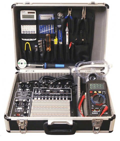
Finally, PRESSON breadboard circuit modules are ideal for use with portable trainers, such as
that shown below.

Assembled PRESSON breadboard modules can fit easily into the breadboard section of the
portable trainer shown above, while PRESSON freestanding modules can connect easily to
the DC power sources provided at the portable trainer console.
Click here to learn more about PRESSON kit options.
In closing, it should be stressed that PRESSON Circuit Modules and supporting courseware
could be used in a wide variety of educational and training application. While the kits and
courseware could become supplemental materials within a four-year electrical engineering
program, they could play a more dominant role in a shorter training program for electronics
or mechatronics technicians.

PRESSON courseware could also be easily consolidated into more compact nano degree or micro credential training programs for technicians and engineers already working in industry. For more details, please email us at [email protected].
Back To Blog
